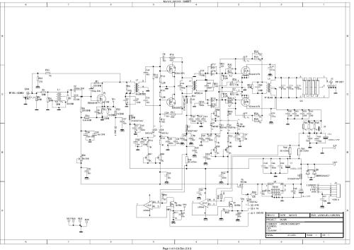
Munin is a 100W RF power amplifier designed by the OpenHPSDR project under the leadership of Kjell LA2NI. Pairs of Mitsubishi RD100HHF1 and RD16HFF1 MOSFET power transistors form the core of this amplifier. Whilst the manufacturer's datasheet publishes data for 30MHz, Munin was designed to complement Penelope, Pennylane and Hermes based transmitters operating on frequencies between 1.8-55MHz.
With a Pennylane and Hermes based transceiver at my disposal I decided to purchase a Munin kit when the opportunity of a group buy organised by members of the OpenHPSDR project presented itself. The kit included all parts, including a heatsink and a copper heat spreader.
Whilst the construction of the amplifier was straight forward, a few obstacles were encountered in the process:
Capacitors C25, C26 and C27 supplied with this kit had voltage ratings of 200V, which in practise proofed to be unsuitable for operation at maximum power output levels. Four 220pf 500V capacitors purchased from Element 14, EPCOS B57703M103G40 P/N 172-2525, were used as replacements.
Placement and soldering of SMD resistors supplied in size 1206 proofed to be very challenging using a fine tipped soldering iron, as the PCB footprints for these components were size 805.
The constrution of L4 proofed to be the greatest challenge. After several failed attempts following the building instructions, I finally used a length of silver plated RG58/U braid and a small length of the original RG58 cable to form the diameter to fit tightly through the binocular former. Solder was then applied to the braid converting it into a solid tube making it easier to feed through the Teflon wire.
The following is a picture showing the assembled amplifier including the modification for bias temperature compensation:
The original Munin design didn't implement temperature compensation for the driver and final transistors. The lack of temperature compensation causes a race condition whereby the bias current would increase as the temperature increases, which in turn would cause a further increase in temperature. To study this behaviour the bias current for the final transistors were set to 1.0 each whilst the driver transistor bias was set to 0.0A at 25C. Munin was then connected to a 13.8V DC supply with the PTT closed and the total bias current of the final transistors was measured at every degree increase in temperature.
Inspired by the design used on Munin 2, the amplifier was modified using two NTC thermistors each mounted to one the final transistors. The NTC thermistors used are a pair of EPCOS B57703M103G40, which were purchased from Element 14 (P/N 171-2525). A modified diagram that includes the modifications of the bias circuitry is show below:
With the NTC thermistors installed, the test was repeated and the bias current versus temperature relationship recorded. The graphic below compares the uncompensated bias current with the compensated bias current.
Whilst use of NTC thermistors results in some improvement, they are unable to closely track the linear characteristics of the final transistor bias current. This is due to the non-linear behaviour of the NTC thermistor devices as can be seen in the following graph:


